Project 6: ESP32 Wi-Fi Led Control Tutorial
Introduction
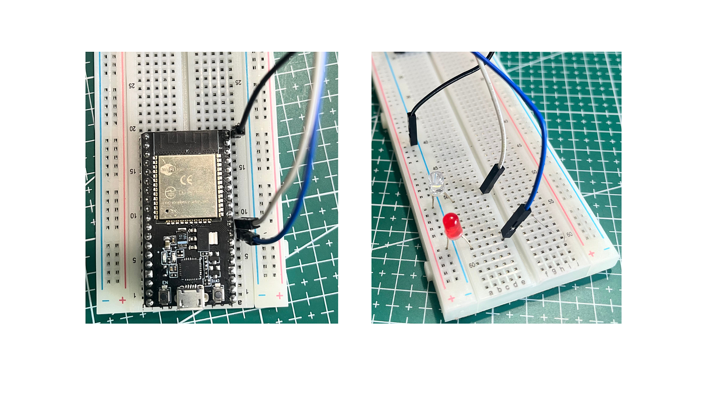
In this tutorial, we will create a simple web server using the ESP32 that allows us to control two LEDs from a smartphone or any device connected to the Wi-Fi network. This project does not use resistors, as we are directly connecting the LEDs to the ESP32.
Components Required
- ESP32 board
- 2 LEDs
- Jumper wires
Circuit Diagram
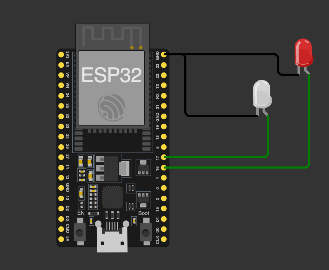
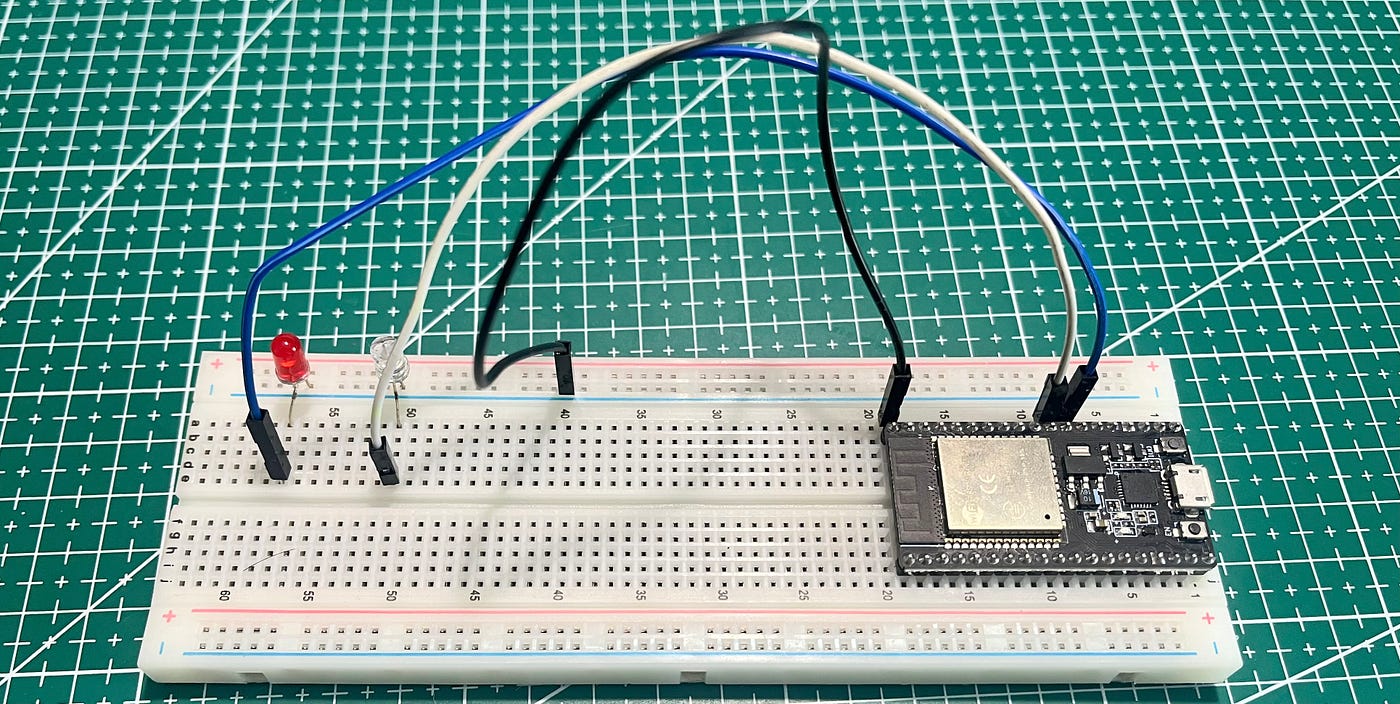
Connect the components as follows:
- LED 1: Connect the positive (anode) leg to GPIO16 and the negative (cathode) leg to GND.
- LED 2: Connect the positive (anode) leg to GPIO17 and the negative (cathode) leg to GND.
Code Explanation
The ESP32 is set up as a Wi-Fi access point, creating a local network. A web server is hosted on the ESP32, where users can control the LEDs by clicking buttons in a web interface.
Code:
// Load Wi-Fi library
#include <WiFi.h>

// Replace with your network credentials
const char* ssid     = "ESP32-Access-Point";
const char* password = "12345678";

// Set web server port number to 80
WiFiServer server(80);

// Variable to store the HTTP request
String header;

// Auxiliar variables to store the current output state
String output16State = "off";
String output17State = "off";

// Assign output variables to GPIO pins
const int output16 = 16;
const int output17 = 17;

void setup() {
 Serial.begin(115200);
 // Initialize the output variables as outputs
 pinMode(output16, OUTPUT);
 pinMode(output17, OUTPUT);
 // Set outputs to LOW
 digitalWrite(output16, LOW);
 digitalWrite(output17, LOW);

 // Connect to Wi-Fi network with SSID and password
 Serial.print("Setting AP (Access Point)...");
 // Remove the password parameter, if you want the AP (Access Point) to be open
 WiFi.softAP(ssid, password);

 IPAddress IP = WiFi.softAPIP();
 Serial.print("AP IP address: ");
 Serial.println(IP);
  server.begin();
}

void loop(){
 WiFiClient client = server.available();   // Listen for incoming clients

 if (client) {                             // If a new client connects,
   Serial.println("New Client.");          // print a message out in the serial port
   String currentLine = "";                // make a String to hold incoming data from the client
   while (client.connected()) {            // loop while the client's connected
     if (client.available()) {             // if there's bytes to read from the client,
       char c = client.read();             // read a byte, then
       Serial.write(c);                    // print it out the serial monitor
       header += c;
       if (c == '\n') {                    // if the byte is a newline character
         // if the current line is blank, you got two newline characters in a row.
         // that's the end of the client HTTP request, so send a response:
         if (currentLine.length() == 0) {
           // HTTP headers always start with a response code (e.g. HTTP/1.1 200 OK)
           // and a content-type so the client knows what's coming, then a blank line:
           client.println("HTTP/1.1 200 OK");
           client.println("Content-type:text/html");
           client.println("Connection: close");
           client.println();

           // turns the GPIOs on and off
           if (header.indexOf("GET /16/on") >= 0) {
             Serial.println("GPIO 16 on");
             output16State = "on";
             digitalWrite(output16, HIGH);
           } else if (header.indexOf("GET /16/off") >= 0) {
             Serial.println("GPIO 16 off");
             output16State = "off";
             digitalWrite(output16, LOW);
           } else if (header.indexOf("GET /17/on") >= 0) {
             Serial.println("GPIO 17 on");
             output17State = "on";
             digitalWrite(output17, HIGH);
           } else if (header.indexOf("GET /17/off") >= 0) {
             Serial.println("GPIO 17 off");
             output17State = "off";
             digitalWrite(output17, LOW);
           }

           // Display the HTML web page
           client.println("<!DOCTYPE html><html>");
           client.println("<head><meta name=\"viewport\" content=\"width=device-width, initial-scale=1\">");
           client.println("<link rel=\"icon\" href=\"data:,\">");
           // CSS to style the on/off buttons
           // Feel free to change the background-color and font-size attributes to fit your preferences
           client.println("<style>html { font-family: Helvetica; display: inline-block; margin: 0px auto; text-align: center;}");
           client.println(".button { background-color: #4CAF50; border: none; color: white; padding: 16px 40px;");
           client.println("text-decoration: none; font-size: 30px; margin: 2px; cursor: pointer;}");
           client.println(".button2 {background-color: #555555;}</style></head>");

           // Web Page Heading
           client.println("<body><h1>ESP32 Web Server</h1>");

           // Display current state, and ON/OFF buttons for GPIO 16
           client.println("<p>GPIO 16 - State " + output16State + "</p>");
           // If the output16State is off, it displays the ON button
           if (output16State=="off") {
             client.println("<p><a href=\"/16/on\"><button class=\"button\">ON</button></a></p>");
           } else {
             client.println("<p><a href=\"/16/off\"><button class=\"button button2\">OFF</button></a></p>");
           }

           // Display current state, and ON/OFF buttons for GPIO 17
           client.println("<p>GPIO 17 - State " + output17State + "</p>");
           // If the output17State is off, it displays the ON button
           if (output17State=="off") {
             client.println("<p><a href=\"/17/on\"><button class=\"button\">ON</button></a></p>");
           } else {
             client.println("<p><a href=\"/17/off\"><button class=\"button button2\">OFF</button></a></p>");
           }
           client.println("</body></html>");

           // The HTTP response ends with another blank line
           client.println();
           // Break out of the while loop
           break;
         } else { // if you got a newline, then clear currentLine
           currentLine = "";
         }
       } else if (c != '\r') {  // if you got anything else but a carriage return character,
         currentLine += c;      // add it to the end of the currentLine
       }
     }
   }
   // Clear the header variable
   header = "";
   // Close the connection
   client.stop();
   Serial.println("Client disconnected.");
   Serial.println("");
 }
}
Usage
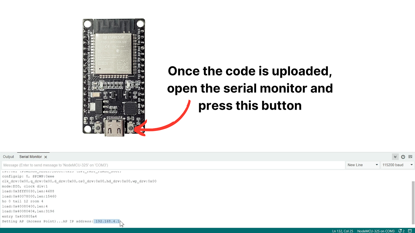
- Upload the code to your ESP32 using the Arduino IDE.
- Open the Serial Monitor to see the IP address of the ESP32.
- Connect your phone or computer to the ESP32 Wi-Fi network (
ESP32-Access-Point). - An IP address will show up on the Serial Monitor after connecting to Wi-Fi. Search that IP in your browser, and it will take you to the web server.
- Use the web interface to turn the LEDs ON or OFF.
Conclusion
This simple project demonstrates how to create a web server on an ESP32 to control LEDs using a phone. No resistors are used in this setup, but for extended use, adding resistors is recommended to protect the LEDs and ESP32.